
Workpiece Material Groups P, M, K, N, S, H: How to Choose Insert Grade & Chipbreaker
Every insert catalogue sorts workpieces into six ISO groups. The group decides your grade family and chipbreaker style before any brand name enters the discussion. Get the group right and most "mystery" tool-life problems disappear; get it wrong and no grade will save the edge.
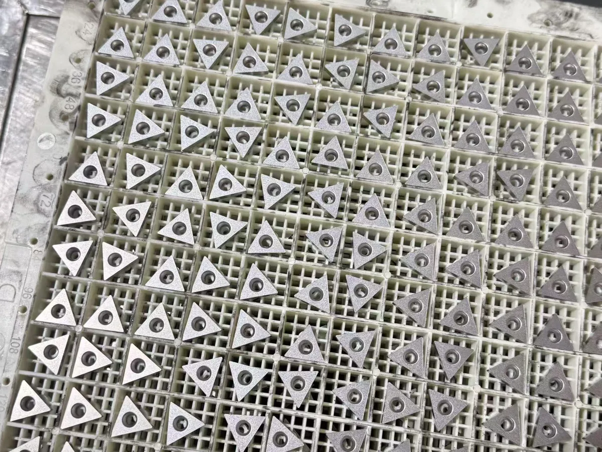
The six groups at a glance
| Group | Materials | What makes it hard on the edge | Grade direction | Chipbreaker direction |
|---|---|---|---|---|
| P (blue) | Carbon & alloy steels | Long chips, crater wear at heat | CVD-coated carbide, medium toughness | Medium geometry, positive chip flow |
| M (yellow) | Stainless steels | Work hardening, built-up edge, heat stays at the edge | PVD-coated, sharper edge, tougher substrate | Sharp, high-rake finishing/medium geometry — never a blunt steel geometry |
| K (red) | Cast irons | Short chips, abrasive flank wear | Wear-resistant CVD, thick Al₂O₃ | Strong, flatter geometry for interrupted surfaces |
| N (green) | Aluminium & non-ferrous | Built-up edge, material welding to the edge | Uncoated or polished/DLC-type, very sharp | High-rake polished geometry |
| S (orange) | Titanium & heat-resistant alloys | Very low heat conductivity, edge notching | Sharp PVD, heat-resistant substrate | Sharp geometry, controlled feed |
| H (grey) | Hardened steels (>45 HRC) | Extreme abrasion at the edge | CBN or ceramic territory | Small, strong edge preparation |
Six-step selection (the order matters)
- Shape & corner angle — 80° (C/W) for strength in general turning, 55° (D) for profiling access, 35° (V) for fine profiling, 90° (S) for facing and heavy cuts, 60° (T) as an economical middle ground.
- Size (IC) — as large as the cut depth and part allow; a bigger IC carries a stronger edge and a bigger seat.
- Chipbreaker working range — every breaker works inside a feed × depth window: finishing geometries at low feed/depth, medium in the middle, roughing at high feed/depth. Running a finishing breaker at roughing feed is the most common cause of "bad inserts" that are actually misapplied inserts.
- Nose radius — 0.4 for finishing and slim parts, 0.8 as the general default, 1.2 for heavy cuts on rigid setups. Radius too large for the machine shows up as vibration, not wear.
- Grade by group — pick the group first (table above), then the toughness position inside the group: lower number = harder/more wear-resistant (finishing), higher number = tougher (roughing, interruptions).
- Entering angle & holder — the holder sets the angle (typically 95° for CNMG-type work); confirm the insert seats in your holder system before comparing prices.
Three failures this prevents
- Built-up edge on stainless — usually a blunt steel chipbreaker or too-low speed; switch to a sharp M-class geometry before blaming the grade.
- Edge chipping in cast iron — usually a finishing geometry in an interrupted cut; move to a stronger K geometry and tougher grade position.
- Crater wear on steel — heat concentration; a CVD grade with Al₂O₃ is the P-group answer, not a harder feed.
Searching in German?
German terminology: indexable inserts for turning are Wendeschneidplatten drehen, and carbide inserts are Hartmetall-Wendeschneidplatten. The six material groups work exactly the same in German catalogues — the letters P, M, K, N, S and H are identical, and a code such as CNMG120408 is read the same way. If you send your inquiry in German, include the full code and your workpiece material as usual; we reply with the matching check for your holder and operation.
Tell us your group, we do the matching
Send your workpiece material (or just the group letter), the code you run now, and your holder — we will reply with the matching chipbreaker and grade options we can supply and a trial plan you can score by parts per edge. WhatsApp: https://wa.me/8617745168691 · Code decoding: /blog/how-to-read-insert-code · Sizes: /guides/insert-size-chart